White Rodgers Fan Center Relay Wiring Diagram

90 113 White Rodgers Fan Control Center Arnold S Service Company Inc
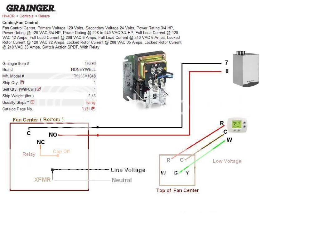
Diagram White Rodgers 90 113 Wiring Diagram Full Version Hd Quality Wiring Diagram Diagramofbrain Bjoly Photographie Fr

A C Stopped Working After A Burning Smell Doityourself Com Community Forums

Https Encrypted Tbn0 Gstatic Com Images Q Tbn 3aand9gcrbcmsku Juakvwl1tdyoxszbmsbyapmo020q Usqp Cau
Central Ac Relay Wiring Diagram Honda 700xx Wiring Diagram For Wiring Diagram Schematics

Vg 8989 White Rodgers Humidifier Wiring Diagram Download Diagram

Read more billyhvac.
White rodgers fan center relay wiring diagram.
Honeywell L4064b Combination Fan And Limit Control How To Set The Temperatures And Limits On The Furnace Fan Limit Switch Control

Emerson 90 113 Fan Control Center Youtube

Sa 0835 Mars 90 340 Relay Wiring Free Diagram

Heat Exchanger In Furnace Fan Only To Run On Call For Heat Hearth Com Forums Home
Source : pinterest.com
